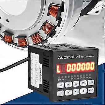
Beschrijving
Single Axes Stepper Motor Programmable Controller
Features:
Instruction features: arbitrary programmable (can achieve a variety of complex operations: positioning control and non-positioning control).
Maximum output frequency: 40KHz (especially suitable for controlling subdivision drive).
High output frequency resolution of which is as accurate as 1Hz.
Multiple working status including automatic running state, manual running state, program editing state, parameter setting state.
8-bit digital tube display, manual/ automatic state display, run/ stop state display, step/ count value/ program display, edit program, parameter display, input/ output state display, CP pulse and direction display.
Specification:
Instruction Specification:Arbitrary Programmable.
Max Output Frequency: 40KHz.
Output Frequency Resolution: 1Hz
Program Number:99
Input:6( Optoelectronic Isolation)
Output:3( Optoelectronic Isolation)
Continuous Displacement Range:-7999999~7999999
Working Status: Automatic running state, manual running state, program editing state, parameter setting state.
Rise and fall curve:2(Optimized)
Display Function:8-bit digital tube display, manual/ automatic state display, run/ stop state display, step/ count value/ program display, edit program, parameter display, input/ output state display, CP pulse and direction display.
Automatic operation function: It can be edited, and the start and stop of automatic operation can be controlled by the panel key and the level of the terminal.
Manual operation function: Adjustable position (manual click-to-move speed and click-to-move steps can be set).
Parameter setting function: can set take-off frequency, speed curve, reverse clearance, manual length, manual speed, interrupt jump line number and return speed.
Program editing function: can be inserted arbitrarily, delete modifiable program.The utility model has the functions of skip-line number, 0 data determination, ultra-long statement number and ultra-short judgment function.
0-return function: can automatically return to 0 in both directions.
Programming instructions: a total of 14 instructions;technical support.
External operation function: Through parameter setting and programming, external interrupt operation can be performed by adding switch on A operation and B operation terminal;
The front panel diagram includes:
1. Eight digital tube display
2.6-way input status indicator light
3. Three-way output status indicator light
4. CP Pulse Signal Indicator
5. CW Directional Level Indicator
6. Buttons: There are 10 buttons, and most of them are compound buttons. They have different functions in different states.
The rear panel shows the terminal, including:
1. CP, CW and OPTP are the control lines of stepper motor drivers, which are connected to the corresponding end of the driver respectively.
CP _ step pulse signal
CW _ motor steering level signal
Common positive end of OPTO _ first two signals
The state of CP and CW corresponds to the indicator light on the panel respectively.
2. Start-up: The startup program runs automatically, equivalent to the start key on the panel.
3, Stop: pause the running program, equivalent to the stop key on the panel, and then start again, the program continues to run.
4, A operation and B operation is one of the main features of this controller: for stepper motor, we generally carry out quantitative positioning control, such as control motor at a certain speed to run a certain displacement this way is easy to solve, only the speed and displacement can be programmed.But there are still quite a number of controls that cannot be positioned in advance, such as the control stepper motor running in one direction from the starting point until it comes to a stop after a trip switch, and of course the reverse runs back to the starting point.For example, the stepper motor is required to run back and forth between the two circuit switches n times, and so on.In these operations, we do not know in advance the displacement of stepper motor specific value, and how should be programmed?This controller uses: "interrupt operation", which we call "A operation" and "B operation".Take "A operation" as an example, the workflow is: When the program is running, if the "A operation" again signal input, the motor to reduce speed stop, the program interrupted here, the program memorized the coordinates of the interrupt, the program jumped to the "A operation" entry address specified in the program to run the program.
5. Input 1 and input 2 by switching the input end.
6. Output 1, output 2 and output 3.
7. COM +, COM-I/ O switch quantity external power supply, this power supply is DC12V/ 0.3 A, COM + is positive end, COM-negative end, this power supply is provided by internal isolation of the controller.
Input signal and output signal interface circuit:
The "start-up", "shut down", "A
-
Fruugo-ID:
407470997-863572436
-
EAN:
4631329770259